
Profile Projector Measuring systems
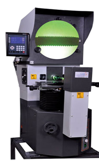
Profile projector measuring systems, also known as optical comparators, are essential tools in precision engineering and manufacturing. These systems are designed to magnify the image of a workpiece, allowing for detailed measurement and inspection of its geometry. They play a crucial role in quality control by enabling engineers and technicians to verify that components meet precise dimensional specifications, which is vital in industries such as aerospace, automotive, electronics, and medical device manufacturing.
A profile projector works on the principle of projecting the shadow of an object onto a screen through an optical lens system. The workpiece is placed on a stage that can move horizontally and vertically, and the shadow is magnified and displayed on a screen. This magnification can range from 10x to over 100x, depending on the system, allowing for detailed inspection of even the smallest features. The screen typically has a grid or crosshairs, which can be used to measure dimensions, angles, radii, and other geometric features directly from the projected image.
One of the key advantages of profile projectors is their non-contact measurement capability. This means that delicate or soft materials can be measured without the risk of deformation, which might occur with contact-based measurement systems. This feature is particularly useful in the inspection of thin or fragile components, such as gaskets, seals, and other parts that could be easily damaged by touch.
Profile projectors are also highly versatile. They can be used to measure a wide variety of parts, from simple shapes like circles and squares to complex profiles with multiple curves and angles. The systems are equipped with precise micrometers or digital readouts, allowing for accurate measurement of linear dimensions. Advanced models may also include software that can automate the measurement process, store data, and generate reports, thereby increasing efficiency and reducing the potential for human error.
Another significant benefit of profile projectors is their ability to compare a workpiece against a standard or blueprint. By overlaying a template or a CAD drawing onto the screen, technicians can visually compare the part being inspected with the desired specifications. Any deviations from the standard can be quickly identified, making profile projectors an effective tool for both inspection and reverse engineering processes.
MODEL EL 250
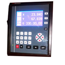
Features:
- LCD screen
- X and Y axes Linear Measurement
- Q Axis (Angular Interface)
- Construction of Angle between Two lines
- Reset of Axes, Inch MM, Absolute Increment
- Circle radius and diameter measurement
- Center distance between Two Circles calculation
- Resolution 0.001mm Linear
- Resolution 0.01Deg. Angular
MODEL EL 530
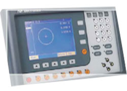
Features:
- LCD screen with Graphical Element display
- Feather touch keypad
- X and Y axes Linear Measurement
- Q Axis (Angular Interface)
- Preset and Reset of Axis, Inch MM, Absolute and Increment
- All 2d Geometrical elements measurement like Point, Line, Radius (Diameter) and Angle etc.
- Construction of Intersection Point (Between Two Measured Line), Circle (PCD), Angle (Between Two Measured line), Line (Between Two Measured Point or Circle) etc.
- Skew feature alignment of component (Co-ordinate orientation)
- Tolerance input.
- PC interface by USB with interface software for Report Print and DXF output
- Resolution 0.001mm Linear
- Resolution 0.01Deg. Angular
- PC to be arranged by customer
MODEL DPS 200
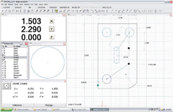
Features:
- Windows 7 Compatible
- X and Y axes Linear Measurement
- X and Y axes Linear Measurement
- Q Axis (Angular Interface)
- Preset and Reset of Axis, Inch MM, Absolute and Increment
- All 2d Geometrical elements measurement like Point, Line, Radius (Diameter) and Angle etc.
- Construction of Intersection Point (Between Two Measured Line), Circle (PCD), Angle (Between Two Measured line), Line (Between Two Measured Point or Circle) etc.
- Skew feature alignment of component (Co-ordinate orientation)
- Tolerance input.
- PC interface by USB with interface software for Report Print and DXF output
- Resolution 0.001mm Linear
- Resolution 0.01Deg. Angular
- PC to be arranged by customer